

Cold Climate Installations
Water will circulate to the SANCO2 heat pump, which is mounted outside. It’s important to take appropriate actions for cold-climate installations to mitigate the risk of water freezing in the pipes and the heat pump. Failure to do so could lead to damage and operational issues.
SANCO2 Freeze Protection Approaches
SANCO2 provides the following approaches to mitigate water freezing in the heat pump. The SANCO2 documentation of these approaches can be found here:
- Minimize the length of piping outside
- Automated freeze protection control program built into the heat pump
- Heat tape on exterior pipework
- Automated freeze protection via drain valves when there is a power outage
- Manual freeze protection when there is a power outage.
Submittal sheets for the recommended heat tape (FG2-6L or FG2-12L) and drain valves (ECO-FPVKT-SMTW) can be found here.
Cold Climate sensors
In a cold climate, directly measuring the heat output of the SANCO2 enables better control of the state of charge of the thermal battery.
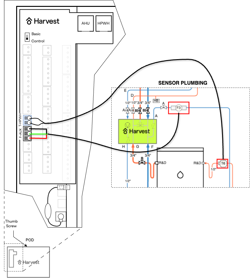
Install and wire the flow meter (F3) and the temperature sensor (T6), provided as part of the sensor kit, as shown in the figure below.
Using an Electric Tank Booster
A tank booster may be added to the Harvest system to help maintain warm water in the hydronic system if the outdoor temperature drops below -25°F, at which point the SANCO2 heat pump will no longer be able to produce hot water.
In addition, an electric tank booster can be used to extend the hydronic storage capacity of a Harvest system. This can be beneficial to meet the home heating load if the capacity of the auxiliary DX heat pump drops due to low outdoor temperatures.
The booster will turn on when tank thermal storage is depleted (specifically, whenever flow > 0.30 gpm and inlet temperature < 115°F).
There are two primary choices for an electric tank booster:
- RHEEM RTEX-AB7 7.2 kW booster - 30A breaker and 50°F temperature rise at 1gpm
- RHEEM RTEX-11 11 kW booster - 50A breaker, and a 50°F temperature rise at 1.5gpm
Plumbing Diagram
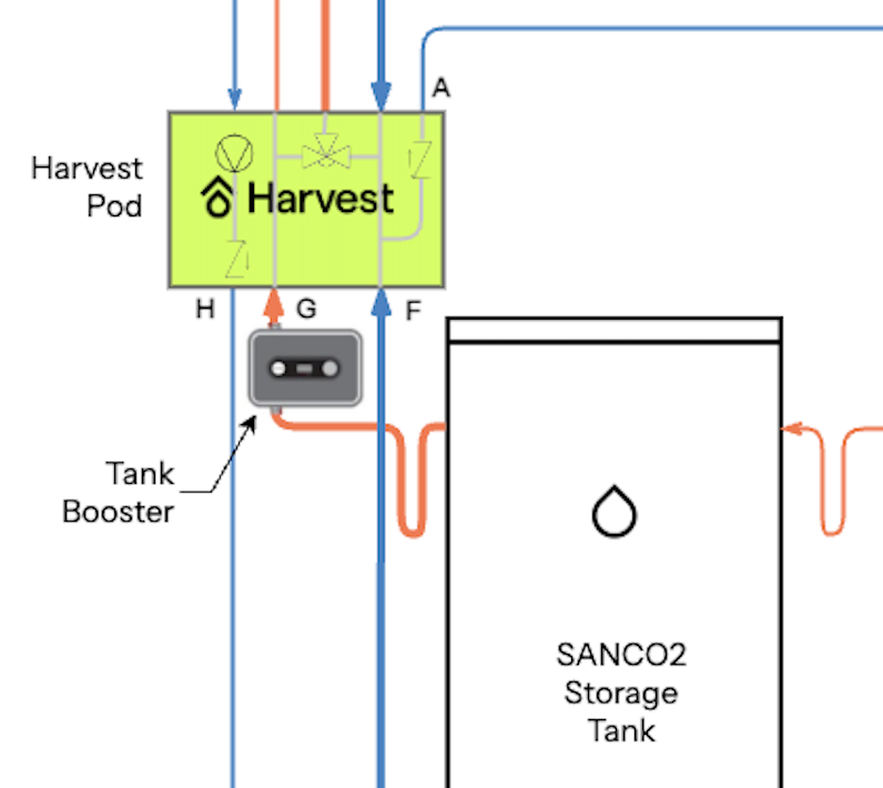
- 14 in. of straight pipe clearance is required for installation below the Harvest Thermal Pod.
- 6 in. of clearance is required on the front and sides of the booster for service maintenance.
High Voltage Electrical Wiring
Install a new disconnect box connected to the main panel and located near the booster
Connect booster L1, L2, G terminals to the disconnect box. Do not use the T1 or T2 terminals.
If you are using the RTEX-AB7 booster, the Harvest Pod can provide additional control of when this unit is powered by installing the RIB24Z relay provided as part of the Booster install kit:
- Splice L1 with one of the RIB24Z relay’s blue wires (blue wires are the NC relay connections).
- Connect the other RIB24Z relay blue wire to the disconnect.
- Do not use the orange wires (NO relay connection)
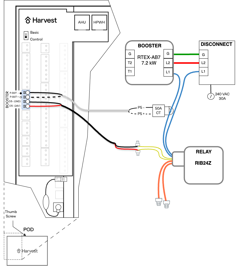
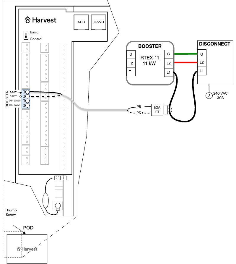
Low Voltage Electrical Wiring
Install the 50A CT, provided in the Harvest Booster Install kit around the wire going to the L1 terminal.
Using 18-4 AWG wire, follow the figure below to connect the CT to the Pod
If you are using the RTEX-AB7 booster, the Harvest Pod can provide additional control of when this unit is powered by wiring the RIB24Z relay as follows:
- Use the other two wires from the 18-4 AWG wire to connect the RIB24Z relay yellow control wires to the Pod.
Booster Setup
Energize the booster and program it with the settings below.
- To cycle through menu options or adjust a setting, rotate the knob on the front of the booster.
- To enter a menu option press the control knob.
| Setting | Value |
|---|---|
| ACTIVATE | 115 |
| MAX TEMP | 130 |
| VACATION | No |
| ECO MODE | No |